Output shift register
Moving directly to the patch-bay matrix circuit turned out to be overreaching. So I stepped back and tested the components separately. First, we made sure the output shift registers were doing the right thing. After some gnashing of teeth, I realized I was loading the wrong sketch. With the right sketch, it worked like a champ. All 16 LEDs lit up in order. |
| Output shift register circuit with full array of test LEDs. See pp. 436-441 in Drymonitis. |
Input shift register
The real problems were in the input shift register. A resistor had a bad connection. With that fixed, its test circuit worked. |
| Input shift register circuit with push buttons for testing through Pure Data. See pp. 430-436 in Drymonitis. |
Patch-bay matrix
Putting these bits together, we get a working 16-input, 16-output patch-bay matrix. This sometimes gets a little noisy, with false connections detected and then usually corrected. But restarting the patch seemed to quiet it down.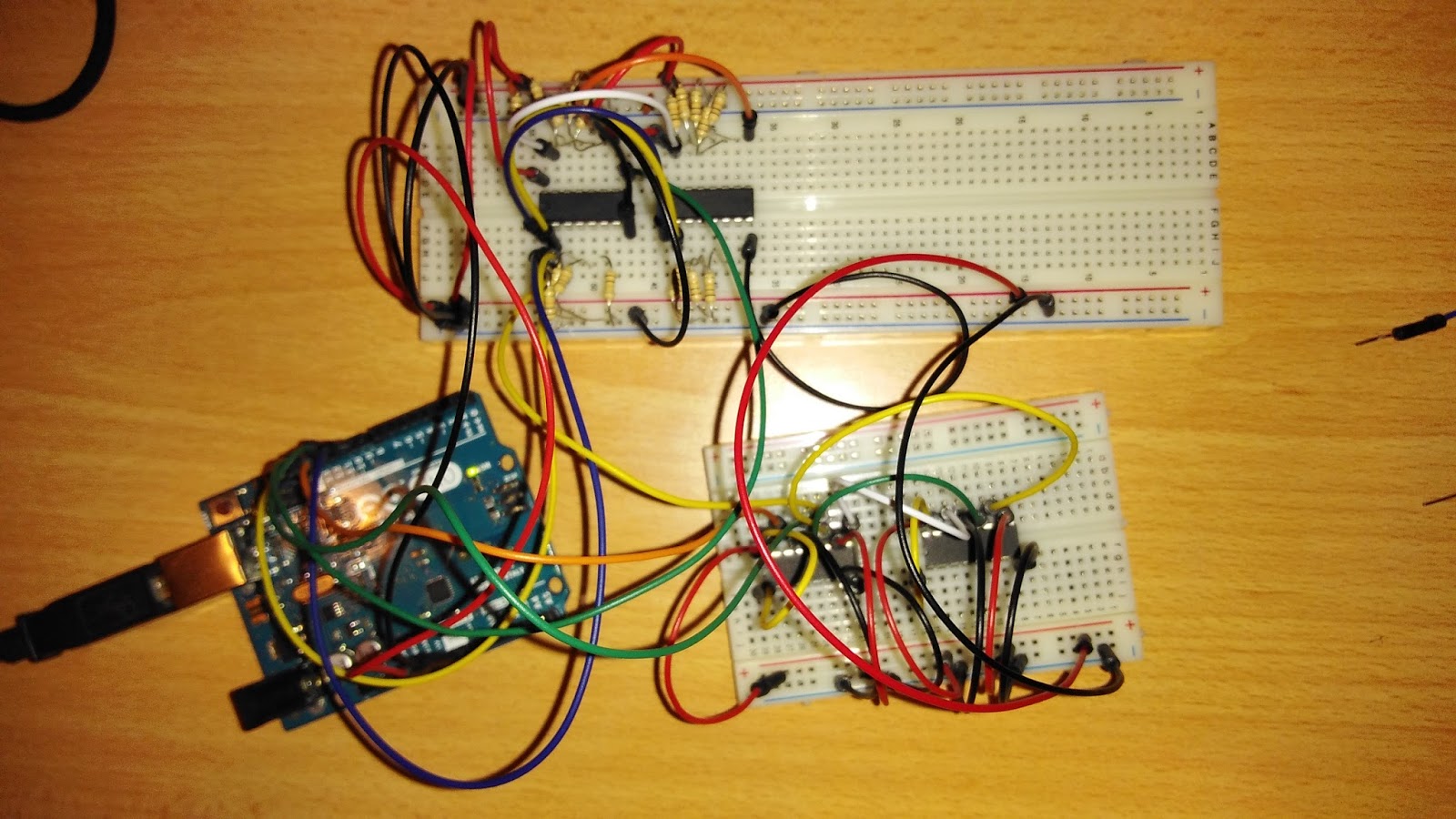 |
The plan now, for the first implementation at least, is to have two input shift register ICs (for the hands) and 11 output shift register ICs (for the keys). The Fritzing diagram shared earlier has this the other way around. The output circuit is simpler and requires no resistors or capacitors. This will shorten the part list. I am not sure which way is more performant. I think removing the capacitors will help performance, but it probably won't matter much.
Finger-key interface (using mini keyboard)
Ignoring scalability, the last bit in the hardware proof of concept is to prototype (however crudely) the patch cord to be formed by connecting a wire emanating from a conductive surface on a given key to one attached to an individual finger.
Solder 16x16 patch-bay matrix circuit
[WE ARE (still) HERE ]
I am a bit concerned about noise in the circuit. Solid connections should mitigate some of the noise, I hope. Also, the dimensions of the separate power supply will not fit on the narrower breadboard-like solderable circuit boards I have purchased. We could leave it on a breadboard, I suppose. I was also surprised to see its LED light up dimly when it was connected to the patch-bay matrix. I took it out in the picture above because I was afraid this phenomenon was contributing to the noise in the circuit. We will need to reintroduce this in the soldered circuit, as I don't think the Arduino can power the complete circuit. But I think this power supply (with the 2 amp 7 volt DC adapter I am using) can power the whole shebang.UPDATE 2016-06-01
We have soldered two boards to implement a 16x48 patch bay:

The power supply won't fit on the protoboards, so we keep it on a breadboard:

The more complicated input shift registers are used for the fingers:


Unfortunately, the "noise" we noted earlier and hoped would be mitigated with a more solid circuit seems instead to be amplified. Or something isn't soldered correctly. If the state of the connections does not change, the output should not change. But we are seeing a lot of output.
I have moved back to the breadboard and will step through the software "sketch" to see what I can see.
UPDATE 7 June 2016
We have a working patch-bay matrix for one input chip and three output. There is apparently something wrong with the daisy chaining of the input shift register component. The plan is now to implement something end to end for one hand.
Debug the sketch
UPDATE 7 June 2016
We have a working sketch for one hand that produces human readable serial output that seems to reflect fingerings accurately.
MIDI processing and event time-stamping
The idea is to monitor the following:
- Fingering connection change events
- MIDI note-on and -off events
- MIDI program change events
UPDATE 7 June 2016
I punted on Pure Data. I have a multi-threaded Python script that monitors the Arduino serial output and the MIDI input and applies a microsecond timestamp uniformly to both. This should be enough for us to post-process the data to determine fingerings. The exact logic of how that should be done is left as an exercise for the writer.
Foil's war
Now we move to the full size keyboard. The plan for applying foil to the keys was to use copper foil tape for the white keys and aluminum foil tape for the black keys.
To make the connection from the foil to a (stranded) copper wire, I planned to solder the wire to a small piece of tape and then stick this tape on the key foil. This seems like a potential problem area as we are relying on the adhesive to make this connection with a moving part. Soldering directly a wire directly on the foil either before or after might be a better approach.
It might also be more effective to use thicker metal foil and apply contact cement ourselves. This might help us position precut (and pre-soldered?) foil pieces, as the cement will take some time to dry.
Another idea is to crack open the keyboard enclosure and move the connection (and maybe our entire circuit) inside the enclosure. This would be elegant, but we don't know how this will fit. And, while this does seem to protect us from accidental bumps and things getting unstuck, fixing any problem that does occur will be a time-consuming affair. Just a thought.
Do we need to use vegetable oil to solder the wire to the foil?
Do we need to use vegetable oil to solder the wire to the foil?
We start foiling 16 keys for the initial 16x16 circuit.
UPDATE 7 June 2016
We have foiled about 3/4 of the keys. Here are some pictures


UPDATE 7 June 2016
We have foiled about 3/4 of the keys. Here are some pictures


A feast of wire (crimping my style)
We create ribbon cables and connectors that allow us us to reduce strain on the key wire connections and foil adhesive and easily to detach the keys and the finger assemblies from the circuit. Start with end to end solution for the 16x16 (10x16) circuit.
All connections to key foil and finger cots should be with stranded wire. The other ends of finger wires will feed 4-wire crimp connectors. In the likely event that our circuit will be housed outside the keyboard's own enclosure, the other ends for key wires will feed 8-wire crimp connectors, which will be firmly attached to the outside of the keyboard enclosure to reduce potential strain on the foil connections.
The original plan was to use banana plugs for individual finger connections to the circuit board. This will be abandoned in favor of crimp connectors interfacing with IDC connections and ribbon cables.
UPDATE 7 June 2016
We are booting on the ribbon cables for the key connections. We plan to mount the boards on the back of the music stand and connect directly to it using Pololu jumper connector housings. We don't need long run ribbons. Here is a picture of what we plan to do for the key harnesses:

Proper finger harness
Latex cots need to have conductive material (either foil or graphite-infused contact cement) applied and attached to (flexible multi-stranded) wires. The wires need to be collected at the wrist with medical tape . Also at the wrist, crimp connectors should allow for easy attachment to (and detachment from) ribbon cables. These ribbon cables will be connected to the male header pins on the input shift register component.
This is probably going to take some iteration/experimentation to get right.
UPDATE 7 June 2016
Here are two options for the end to-end finger connections, one which requires soldering and one which does not.
UPDATE 7 June 2016
Here are two options for the end to-end finger connections, one which requires soldering and one which does not.
 |
| Soldered finger connection assembly. |
 |
| Solderless finger connection assembly. |
Add one output shift register IC at a time and test
Yeah, what he said.